 |
|
|
 |
Products - Purified
Water Storage & Distribution System |
| |

|
Click on the image/thumbnail to englarge it |
|
| |
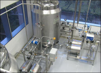
Hydrocons delivers latest concepts for
Purified water storage & distribution
system. Purified water generated from purified
water generation system shall be transferred
to the Purified water storage tank This Purified
water from the storage tank is then re-circulated
in a closed loop to various user points with
the following features.
- The storage tank assembly consisting
of
- SS316L wetted parts, Jacketed,
SS Cladded.
- Dished ends at bottom for
complete drainability and at top to avoid
stagnation.
- Spray ball located at the
center nozzle (loop return) on the manhole
for continuously wetting
all the contact parts
on the top surface of the tank including
the manhole internal surfaces.
- Sanitary nozzles for feed,
re-circulation, vent, pressure gauge,
level switch, spare nozzles
on the top (manhole)
and outlet at the bottom.
- Surface finish of less than
0.4 Ra inside and mat finish on outside
surface.
- Sterile vent filter on the
tank top.
- The distribution pump consisting
of the following features
- SS316 L wetted parts.
- Mono-block/ vertical multistage,
centrifugal type.
- Casing drain sanitary Valve.
- Distribution loop consisting
of the following features
- SS316L, Seamless tubes,
Electro-polished.
- Internal surfaces finish
less than 0.4 Ra.
- Outside mirror polish
- Installed at a slope of
1:100 for complete drainability.
- Properly supported with
SS304 contact parts.
- Dead legs of not more than
3 D.
- No hold up volume in case
of shut down.
- Normal velocity of 2.8 m/s
and during peak load velocity of min 1.2
m/s shall be maintained.
- All possible joints shall
be orbital welded; remaining joints shall
be sanitary tri-clamp
type with silicon gaskets.
- Apart from the above major items,
the system have the following features
:
- The complete storage and
distribution system shall have provision
of hot water sanitization
- Have the necessary pressure
gauges viz. at pump outlet, loop return
and compound
pressure gauge on tank
top
- Conductivity controllers
in loop supply.
- Differential pressure sensors
& transmitters are provided in loop
system.
- Temperature sensors in tank
bottom & loop return.
- Level controller on tank
for pump controlling and feed control.
- Sanitary UV Unit to control
microbial load.
- Flow transmitters in loop
return to monitor flow rate / velocity.
- Auto Dumping valve in loop
supply for high conductivity.
- Auto Back Pressure Valve
in loop return to regulate pressure and
flow.
- The complete system shall
be controlled by PLC based control panel
with datalogging
facility.
|
| |
|
| « Top » |
| |
|
|
|
|
|

